Linear vs Nonlinear FEA Analysis: Critical Limitations in Structural Design
Travis Stephens
8/26/2025
Introduction
Finite Element Analysis (FEA) has become the standard for calculating airframe internal load distributions, enabling engineers to solve the statically indeterminate problem under multitudes of loading conditions. However, the choice between linear and nonlinear analysis methods can have profound implications for safety and design adequacy. While linear analysis offers computational efficiency and simplicity, there are critical scenarios where it fails to capture essential structural behaviors, potentially leading to unconservative designs and structural failures.
Understanding the Fundamental Difference
Linear analysis operates under the assumption of small displacements, small strains, and linear material behavior. It assumes that structural stiffness remains constant throughout the loading process and that the principle of superposition applies. Nonlinear analysis, conversely, can account for large displacements, material nonlinearity, and contact conditions, providing a more realistic representation of structural behavior. Optimized aerospace designs are permitted to buckle up to limit (service) loads provided that the buckling does not cause detrimental, permanent deformation. Geometric nonlinear effects can therefore become critical during conditions that are below limit loads.
Simple Example Case: Simply Supported Beam
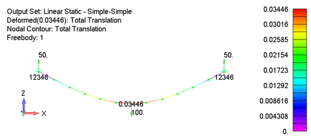
One of the simplest examples of how geometric nonlinearity can significantly affect results can be seen in the case of a simple-simple supported beam with a center load. In the traditional academic case, a pinned support is assumed at one end and a roller support at the other. The roller support is an important detail as it allows horizontal displacement to occur and prevents the development of horizontal reaction load components. The following example demonstrates the classical case along with FEA results from both linear and nonlinear solutions.
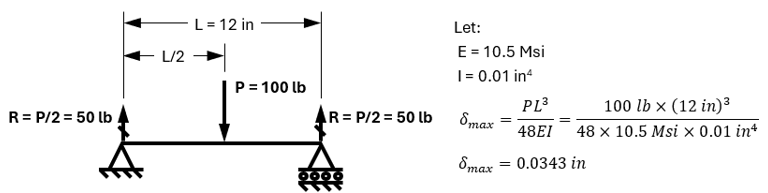
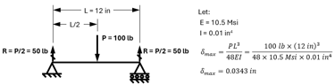

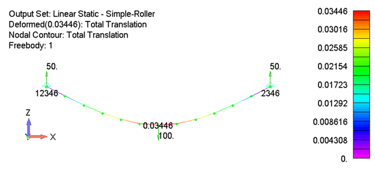
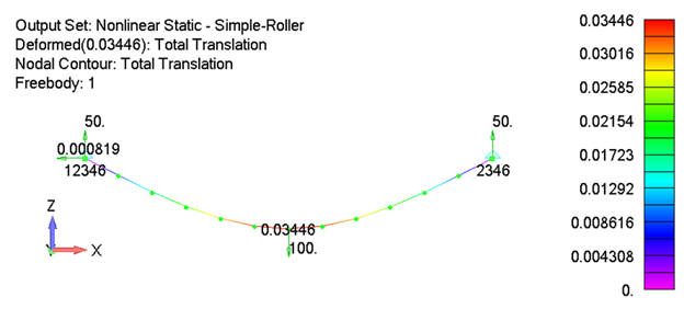
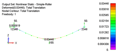
As can be seen, the classical, linear and nonlinear solution results all match each other within in acceptable range. It is also worth noting that the total displacement is well within the range of what would typically be considered “small displacements” for a beam problem.
If everything is left the same except the right support is changed from a roller support to a “fixed” simple support, the linear static solution remains unchanged but the nonlinear results no longer match the linear solution. This is because the linear solution assumes the undeformed shape of the structure only and has no way to capture the axial force that is developing in the beam from the resistance of the beam stretching in the horizontal direction.

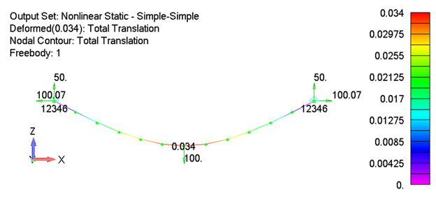
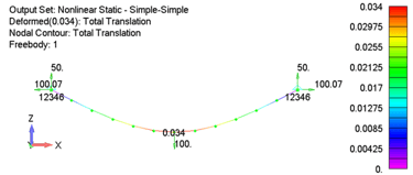
The variation between the linear and nonlinear force resultant vectors at the end of the beam is over 55%. Depending on the actual boundary conditions of the problem at hand, this difference could break the design. In addition, if we assume the beam has a rectangular cross section with a width of 1 inch and a thickness of 0.5 inch, the maximum stress at the center of the beam from the linear solution is 7500 psi while the nonlinear stress is 7615 psi. While this is a modest 1.5% difference, it demonstrates that the linear static stress is an underprediction. As displacements increase more, so too will the error in the linear static solution.
Critical Real-World Case: Membrane Structures and In-Plane Forces
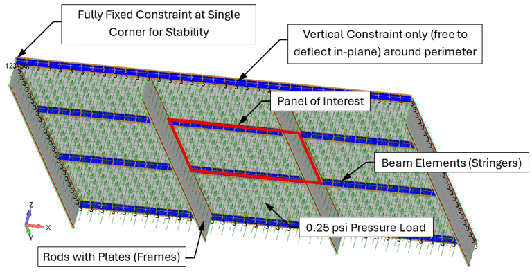
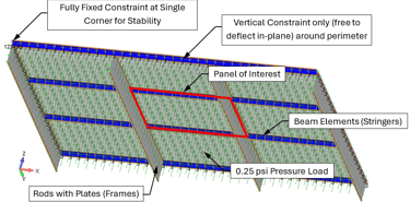
While the prior example demonstrates the error that can result from ignoring geometric nonlinear affects, its application to real world problems can be limited in the sense that many real-world problems can’t be idealized perfectly as a beam, and the boundary conditions are rarely rigid. The following example is of an 8 inch by 12 inch, 0.032 inch thick, flat plate. The top and bottom sides are reinforced with 0.040 inch thick T-section beam elements, and the forward and aft edges are reinforced by rod elements connected to 0.040 inch thick plate elements that are normal to the plane of the flat plate. This type of model is common of what would be used to represent either a pressure bulkhead or skin/stringer/frame in traditional aircraft design and analysis.
To add further validity to the problem, the panel is flanked on all sides by similar panels, and FE boundary conditions are placed a bay away. The model is then loaded with a relatively small pressure of 0.25 psi, to intentionally limit buckling and other nonlinear geometric effects. The following figure shows the model setup, followed by the results for the center panel.
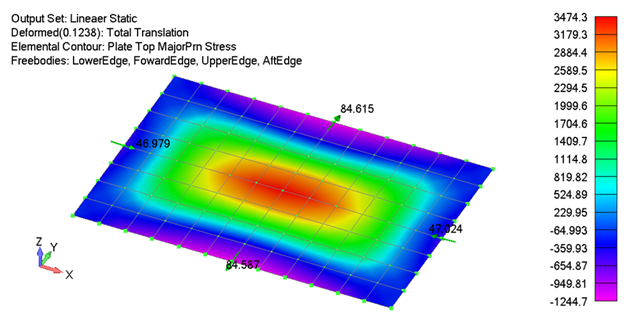
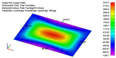
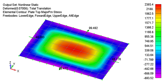
As shown, the difference in results between the linear and nonlinear solutions are substantial. While the linear deflections and stresses may be conservative relative to the nonlinear ones, the stringer forces are underpredicted by nearly 15%. The loads and stresses on the panel were intentionally kept low to demonstrate that even in load cases where forces are below critical buckling or limit loads (such as fatigue load cases), not considering geometric nonlinear effects can adversely affect analysis predictions. Like the beam example, as loads/deflections increase, and in particular when buckling starts to occur, the linear and nonlinear results further diverge from each other.
Regulatory Recognition of Load Redistribution
The critical importance of considering load redistribution (i.e. geometric nonlinear affects) is explicitly recognized in aviation regulations. Both 14 CFR Part 23.301(c) for normal category aircraft and 14 CFR Part 25.301(c) for transport category aircraft require that:
"If deflections under load would significantly change the distribution of external or internal loads, this redistribution must be taken into account."
This regulatory requirement implicitly acknowledges that load paths change during loading and that post-buckling load redistribution must be considered in the design process. Linear analysis alone cannot capture these load redistributions because it assumes constant structural stiffness and load paths.
Design Implications and Safety Considerations
The limitations of linear analysis in regards to changes in geometry throughout loading create several critical design challenges:
Under-prediction of Critical Stresses: In membrane structures, the failure to capture in-plane forces can result in reaction loads and stress levels that are orders of magnitude higher than those predicted by linear analysis.
Incorrect Load Path Identification: Linear analysis may identify critical loads that become less relevant after buckling, while missing the actual critical post-buckling loads.
Inadequate Design Margins: Structures designed based solely on linear analysis may have insufficient safety margins because the actual failure modes and stress states are not properly characterized.
Best Practices and Recommendations
Given the limitations on linear analysis, engineers must carefully consider when nonlinear analysis is not just beneficial but essential. Many aircraft have been designed using linear analysis, but all were accompanied by a multitude of classical theory calculations and robust testing. Historically it was also not uncommon to include healthy safety margins or to overdesign the structure (at least initially) to account for known shortcomings within the structural analysis.
When working with either legacy designs or in particular new designs, it is essential for engineers to understand the limitations of the analysis they are using, and how those limitations relate or affect a particular design they are working on. While a linear analysis may be adequate for one give aircraft model and load condition, it may be woefully inadequate for another.
Computation resources have made running nonlinear analysis fairly practical. Even so, transitioning from linear to nonlinear analysis is rarely a trivial task, and companies and engineers can be discouraged from wanting to do it. This often leads to the question of whether or not it is really necessary to solve the model using nonlinear analysis versus linear analysis alone.
In general, nonlinear analysis due to geometric effects should be considered when (1) membrane action may be significant, (2) when the deformed shape (i.e. incomplete diagonal tension and post-buckling behavior) may cause geometric stiffening or load redistributions paths, and (3) there is not an established history of the linear results being reliable to use. One of the most effective ways to determine whether or not nonlinear geometric affects are appreciable, is by solving the model using both linear and nonlinear solutions and comparing the results. Ideally this should be completed early in the design/analysis phase to help determine the scoop of analysis and testing work that will need to be completed.
Conclusion
While linear analysis remains a valuable tool for preliminary design and situations where its assumptions are valid, engineers must recognize its fundamental limitations in capturing essential nonlinear behaviors. In membrane structures and thin-walled components subject to buckling, linear analysis can be dangerously unconservative, missing critical load-carrying mechanisms and failing to predict actual failure modes.
The regulatory recognition of load redistribution requirements underscores the professional responsibility to use appropriate analysis methods. While there are established classical methods that use linear results to show compliance for geometric load redistributions, these methods contain assumptions and limitations that must be thoroughly understood and proven reliable on a case-by-case basis. Short of having an already established reliable analysis program in place, nonlinear analysis becomes essential to establish the effect of nonlinear behavior on a structure. With computational resources making nonlinear analysis increasingly accessible, nonlinear analysis may become a cost-effective alternative or supplement to more traditional approaches. It also lacks some of the limitations of more traditional approaches thus creating the potential for more innovative designs, or potentially highlighting structural failures or safety concerns that would have otherwise been missed.
Insights
Delivering FAA compliant solutions and taking your team to the next level.
CONTACT
For Services Inquiries
higheraviation@gmail.com
618-713-7890
© 2025 Benny Aero LLC. All rights reserved.