When is short edge distance and fastener pitch acceptable?
Travis Stephens
7/11/2025
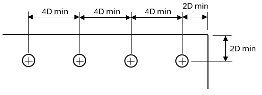
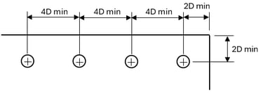
One of the most common design standards throughout the aviation industry is that the distance from the center of a fastener hole to the edge of a part should be no less than two times the nominal diameter of the fastener. Similarly, within a row of fasteners, the center-to-center fastener distance should be no closer than four times the nominal fastener diameter. For example, for a #4 or 4/32” (0.125”) rivet the minimum edge and pitch distances would be 0.25” (0.125” x 2) and 0.5” (0.125” x 4) respectively.
A couple of things to note, strictly speaking the standard is based on the nominal diameter of the fastener. If you are looking at fastened joint strengths, and there is a note that strengths were developed based on 2D edge distance, the implication is that the distance is 2 times the nominal fastener size. In the case of bolts, the actual fastener diameter may be less (ex. ¼” nominal diameter NAS6204 bolt has a shank diameter of 0.2495” – 0.2485”) and the in the case of rivets the final driven diameter will be more (ex. 4/32” nominal diameter rivet final shake diameter typically 0.129” – 0.133”).
With the exception of interference fit fasteners, the fastener’s hole will typically be larger than the nominal fastener diameter. It is still customary to use the nominal fastener size when determining pitch or edge distances, however it is generally acceptable to use the hole size within engineering strength analysis. A case where this does not hold true is in comparative strength analysis where a larger hole size should never be assumed as being used to establish the original design strength. In the case of fatigue and damage tolerance analysis, the actual hole size should always be used.
One last thing to note about measuring distances is the case of dissimilar size fasteners. When this case occurs the nominal diameter of the larger fastener should be used to determine minimum pitch distance. That said, as will be discussed briefly in the following, often times engineers will be able to allow a shorter distance.
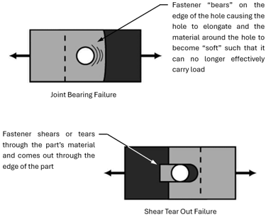
When 2D edge distance or 4D pitch cannot be maintained due to either practicality or a repair situation, some of the first things a stress engineer will look at are the load on the joint, the material type, and sheet or plate thickness. The strength of the fastener itself is not reduced by being near an edge or having a short pitch. With less material between the fastener and the edge of the part or an adjacent fastener, the joint bearing strength and the load required to shear the fastener out of the side of the sheet or into the next fastener are reduced.

Engineers can use calculations to estimate what these reductions in strengths are and compare them to the strength of the fastener itself or the actual applied loads on the joints. If the fastener strength or the applied loads are less than the reduced bearing and shear tear out strengths, then in many cases, the short edge or pitch distance can be acceptable.
The calculated reduced joint strengths are not perfect and cannot be used blindly. Engineers should always remain cognizant that there is a margin of error within the calculations and assess the risk of that error in the particular application. Different factors to consider when making the assessment are:
Magnitude of the load relative to the calculated reduced bearing and shear tear out strengths. If the load is 50% or more less than the calculated strengths, the minimum strengths within the margin of error is unlikely to dip below the applied load.
Direction of the applied load. Bearing and shear tear out assumes the load is applied directly toward the edge of the part or inline with the adjacent fastener. If the load direction is parallel to the edge of the part or perpendicular to the fastener row, then bearing and shear tear out failures are not likely.
Number of times the short edge or pitch distance will occur. The same as standard joints, there is statistical variation in the strength of similar short edge/pitch distance joints. Replicating a short edge/pitch distance design (i.e. in a production environment) increases its exposure to the realization of a failure at the lower end of the probability curve.
Criticality of the part. While all structural parts are required to sustain loads they are expected to experience in service, failure of a secondary or tertiary part is not as critical as failure of primary structure or principal structural elements.
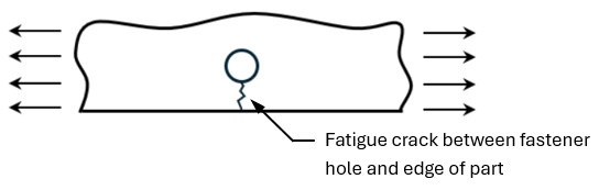
On item 4 from above, when dealing with primary and principal structural elements, engineers must consider additional factors beyond bearing and shear tear out. Many structural failures that happen occur as a result of repeated loading over time. This isn’t as much of a concern for secondary and tertiary parts where the failure would not be catastrophic, but is of upmost importance for principal structural elements and primary structure where the failure is more likely to lead to loss of lives and complete destruction of the aircraft. Short edge and pitch distances adversely affect fatigue life. While short edge distance and pitch distances can be permitted in principal structural elements and primary structures, they require a much higher degree of engineering substantiation and scrutiny than those in secondary or tertiary structure. Because of the increased risks and the level of effort involved to ensure short pitch and edge distances are safe in principal or primary structure, they are generally best to avoid if possible.

In summary, in a number of cases short fastener edge and pitch distances can be permitted, however there are a number of factors that engineers must consider. A better understanding of these factors can help provide clarity as to why in some cases engineers quickly permit the allowance of below standard distances, while in others they provide strong resistance or outright refusal.
Insights
Delivering FAA compliant solutions and taking your team to the next level.
CONTACT
For Services Inquiries
higheraviation@gmail.com
618-713-7890
© 2025 Benny Aero LLC. All rights reserved.